Disclaimer: The feature described in this post requires either the ultimate or the premium editions. For a good visual of the edition differences see the visual studio 2010 editions poster (http://vs2010quickref.codeplex.com/)
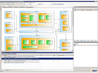
The layer diagram is a new feature in visual studio 2010 which allows an architect to visualize applications layers and the desired communication and dependencies between the layers and components. Big deal right – you can do that in power point if you had to. Ah but the goodness with the layer diagram is that it can enforce the dependencies between layers. Therefore it is possible to stop rouge leader from having the UIX layer from accessing the data layer directly.
Getting Started
- Select New Diagram from the Architecture menu in visual studio

- Select Layer Diagram and give it a name. I recommend also adding a new project that will hold your various diagrams.

- Now using the toolbox, you can add you application layers and the dependencies between them

- To enforce these dependencies you can associate your solution projects to the appropriate layer. Using the solution explorer drag each project to the appropriate layer. Each layer will show a count of projects associated with the layer.

- This view shows how many projects are associated to each layer, but to see the actual projects you need to open the layer explorer

- The layer explorer:

- You can now have visual studio validate that your solution matches your architecture by opening the context menu and selecting validate architecture. This will return errors if you solution validates your diagram.

- Tie the validation to your builds and TFS work items:
- You can modify your modeling project to validate on every build
- If using CI (Continuous Integration) with TFS or MS Build you can add an option to validate your model with every build.
- You can add work items for each violation
Wrapping it up
I've shown a very basic layer diagram but MS has provided screenshots of the potential diagrams with a true enterprise application
